White Paper: EMP & IEMI Protection Concepts For Transmission & Distribution Substations
Electromagnetic Pulse Protection Concepts
About
EMP, or High-Altitude Electromagnetic Pulse (also “HEMP”), along with other electromagnetic threats, such as IEMI (Collectively known as “E-Threats”), used to be the domain of the Department of Defense. It has become increasingly apparent that civil infrastructure is critical even to the efficient functioning of our National Security. Therefore, the identification of electrical power substations, including microgrids, bears increasing scrutiny when considering EMP/IEMI resilience.
This white paper proposes several concepts, ideas, and design elements for the protection of substations and related electrical power infrastructure both expeditiously and cost-effectively.

The Authors
Thomas Blythe Gaven Industries, Inc.
thomas.blythe@gavenindustries.com +1.724.352.8100 ext. 237
Jonathan Mccune Gaven Industries, Inc
jonathan.mccune@gavenindustries.com +1.724.352.8100 ext. 243
Jonathan Mccune Gaven Industries, Inc
jonathan.mccune@gavenindustries.com +1.724.352.8100 ext. 243
Davidson A. Scott, P.e.Electromagnetic Associates, LLC
1. Introduction
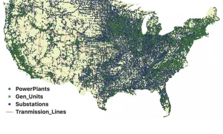
Electrical Power Utilities are complicated and varied entities They include companies that generate, transmit, and distribute their own power, as well as co ops focused on distribution, microgrid operators, transmission-only and generation-only companies that all must interface with what is collectively known as “The Electrical Power Grid”. Each component is required to operate its portion of “The Grid” within certain requirements and is subject to the control of grid managers (often known as “Independent System Operators”, or ISOs). It is a daily challenge to effectively balance expected electrical load with available electrical generation capacity along with reliable reserves to account for unexpected situations. In general, the grid is fundamentally based on “control nodes” which are substations Substations are tasked with adjusting and controling electrical power flowing through them, and they also monitor thousands of parameters so that the power will flow safely.
A substation at its most basic level is a combination of a communications node, stability and control node, and safety/monitoring node. A substation generally is in constant communication with a “Power Control Center” using SCADA protocols.
Many Electrical Utilities initially approach EMP/EM resilience by electromagnetically hardening their Control Centers. This is the ideal approach, as these facilities will be the main point from which post-EMP (or natural disaster) restoration will begin. However, once an EMP event occurs, the control center will be required to communicate with substations and generation stations in order to confirm proper operational functionality, while also facilitating reliable control and providing correct data about the state of all monitored parameters. This includes the operational condition of all transformers and other equipment that are part of the substation.
Substations are designed under a more “conventional” threat environment to have a backup power system With this approach, even if the utility power supply to the substation was completely compromised, communications, control, and monitoring functions would still be available due to the substation’s onsite backup power system. When utility power generation is completely shut down, restoration efforts would be termed “Black Start”. Under a “Black Start” scenario, certain generation stations would be capable of “Self start”, and then they could energize a portion of the grid (through substations) which would be used to start the next generation station until sufficient generation capacity was made available to service expected loads, which would then be connected one-at-a-time until power was restored.
Typical substation backup power durations range from 8 to 24 hours. In other words, utility power must be provided to the substation within that timeframe, or the substation will require on-site manual intervention.
In a likely EMP scenario, it is possible, perhaps even likely (due to generation station damage), that a substation would be without utility power for an extended period of time beyond the design backup. power duration This would severely complicate a “Black Start” scenario post-EMP. This assumes the substationitself survives an EMP event.
Electromagnetic threats, including HEMP/EMP and IEMI are a significant potential impact to electrical infrastructure, particularly substations.
There are no specific requirements for substations to be made “E-threat Resilient” at this time. Resilience, in this regard, is roughly defined as being able to operate before, during, and after an electromagnetic event. Due to decades of experience in shielding, firms such as Gaven Industries have developed techniques and methods to mitigate costs while maintaining Electromagnetic hardness and survivability against all types of E-threat including EMP, HEMP, IEMI, and RF.
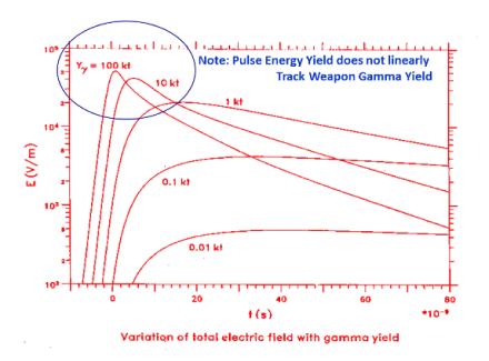
For those who have not been made aware of HEMP/EMP or other electromagnetic threats, a HEMP event occurs when a bad actor detonates a nuclear weapon at an altitude (usually above 20 miles in altitude. There are several different phases of a HEMP event known as "E-1, E-2, and E-3 transients." This paper emphasizes the threat from the E-1 HEMP component, a broad-spectrum high-energy electromagnetic pulse generated when gamma rays from a nuclear detonation interact with the atmosphere This creates a potentially dangerous environment for unprotected electronics or other systems. While the area of the Earth affected is largely dependent upon the height of the nuclear detonation, the energies experienced are not closely correlated with the size of the nuclear device and are remarkably consistent.
For further information on HEMP/EMP, refer to www.gavenindustries.com/shielding-101 as well as information provided by the Department of Homeland Security Office of Science and Technology.
Intentional Electromagnetic Interference or "EM" is a class of electromagnetic threat that can damage. degrade, or disrupt communications, electronics, or other critical systems. This paper focuses primarily on avoiding "damage to systems, however associated risks of degradation and disruption are also essential and are reduced when system damage is mitigated.
Electromagnetic interference (EMI) is unwanted noise or interference in an electrical path or circuit caused by an outside source. It is also known as radio frequency interference. EMI can cause electronics to operate poorly, malfunction or stop working completely. EMI can be caused by natural or human-made sources Using high quality electronics, electrical shielding, and modernerror correction can reduce the impact of EMI.
EMI occurs because of the close relationship between electricity and magnetism All electrical flow produces a small magnetic field. Conversely, a moving magnetic field produces an electrical current. These principles allow electric motors and generators to work Additionally, all electrical conductors can operate as radio antennas High-powered electrical and radio sources can produce unwanted effects in devices far away.
There are some sources in the natural world that can produce powerful enough electric fields to affect electronic devices. Lightning can produce strong electrostatic discharges and magnetic pulses. Solar storms and solar flares emit highly charged particles that can cause problems with satellite and terrestrial communications Cosmic radiation has been known to cause bitlipsin electronics.
Human-made EMI can come from many places High power radio and electrical sources can cause unwanted EMI. Malfunctioning or improperly designed consumer devices can cause EMI in other devices Using an electromagnetic pulse to intentionally induce EMI faults in victim devices is also a possible offensive action.
In the case of IEMI, homemade disruption devices such as pulsers can be built completely of off-the-shelf parts and then set several hundred meters or more away from the intended target with the intent of harassment, degradation, or destruction.
One of the key differences that make IEMI particularly concerning for critical infrastructure is its lower energy nature compared to HEMP. This makes the IEMI threat more likely to be utilized by a bad actor in localized threats. The relatively lower energy levels of lEMlattacks might not cause immediate catastrophic damage on a wide scale, but they can still disrupt critical systems and lead to operational failures. For example, consider a scenario in which a power interconnect substation is targeted by an IEMI attack The attackers generate high-frequency electromagnetic interference that disrupts the facility's control systems, causing outages in electronic transmission and delivery communication systems While the physical infrastructure remains intact, the disruption to electronic systems can lead to compounding problems on a regional level. If coordinated, these sorts of attacks can aggregate to more widespread damage.
Intentional Electromagnetic Interference (EM) refers to the deliberate generation of electromagnetic signals to disrupt or damage electronic systems and equipment It is a subset of Electromagnetic Interference (EMI), which involves the unintended generation of electromagnetic fields that interfere with the proper functioning of electronic devices. IEMI is a form of cyber-physical attack that targets the vulnerabilities of electronic systems by exploiting their sensitivity to electromagnetic fields It's worth noting that IEMI is distinct from Electromagnetic Pulse (EMP), which includes High Altitude Bectromagnetic Pulse (HEMP) and other similar phenomena.
HEMP refers specifically to the burst of electromagnetic energy that occurs as a result of a nuclear explosion at high altitudes. This burst of energy can induce powerful electric and magnetic fields on the Earth's surface, potentially damaging or disrupting electronic systems and infrastructure over a wide area. IEMI, on the other hand, is not inherently tied to nuclear explosions and can be generated by various means, including intentional jamming devices, directed energy weapons, and other electromagnetic sources.
While IEMI and HEMP share some similarities in terms of their potential impact on electronic systems, there are also key differences. One notable distinction is the frequency spectrum in which they operate. IEMI generally operates over higher frequency ranges than HEMP. This can affect the way electromagnetic waves interact with materials and electronic systems.
Here are some key pointsrelated to the differences and similarities between IEMI and HEMP and risk mitigation solutions.
Frequency Spectrum : IEMI generally operates at higher frequencies than HEMP. This can affect the way electromagnetic waves interact with materials and electronic systems Based on the threat being addressed, planners should consider a more comprehensive wide range of frequencies to exclude or a layered defense approach within the shielded environment to defend against HEMP andIEMI.
Remediation Measures : While some protective measures used for HEMP remediation can be adapted for IEMI, the higher-frequency nature of IEMI may require different shielding materials and configurations. For instance, higher-frequency electromagnetic waves might be more effectively absorbed by certain materials Involving a proven shielding industry consultant, such as Gaven Industries, early in a project allows a more integrated solution that can address the most appropriate shielding effectiveness requirement for the system or sub-system.
Undergrounding of Penetrations : One mitigation strategy you mentioned is the undergrounding' of penetrations. This involves placing critical electronic infrastructure below ground to provide passive shielding against. electromagnetic fields. This method can help absorb and dissipate electromagnetic energy, reducing its impact on sensitive systems.
Trade-off between Physical Security and Shielding : In the context of IEMI, there can be a trade-off between physical security and electromagnetic shielding Unlike HEMP, which can affect a larger area, IEMI is subject to the inverse square law and Free-Space Path Loss. This means that the strength of the electromagnetic field rapidly decreases with distance from the source. Organizations may need to balance their physical security needs with the level of electromagnetic shielding required to protect against IEML This may include a layered defense approach as well as strategic planning when locating certain operations within the substationenvironment.
Repeating Waveforms : IEMI threats can involve repeating waveforms, subjecting targeted systems to multiple energy pulses. This can lead to cumulative effects and potentially more extensive damage compared to the single-pulsenature of a HEMP event.
The distinction between Intentional Electromagnetic Interference (EMI) and High-Altitude Electromagnetic Pulse (HEMP) reveals the unique threats they pose to critical infrastructure, IEMIS precision and lower energy nature make it a concerning choice for localized disruptions by bad actors, while HEMP's broad reaching and powerful electromagnetic bursts present a different challenge. Understanding these differences is crucial for effective protective measures, including adapting shielding materials, considering undergrounding of penetrations, and finding the right balance between physical security and electromagnetic shielding. In an era where critical infrastructure relies heavily on electronic systems, recognizing and addressing these nuanced threats is essential for safeguarding vital systems and ensuring their resilience against evolving risks.
Solar storms are naturally occurring space weather events that produce coronal mass ejections (CME) which can travel through space toward Earth When charged particles from CMES hit Earth's magnetosphere and ionosphere, they create a geomagnetic disturbance (GMD) that affects satellites, power grids, communications, navigation, and more When CME-induced GMDS impact the power grid, they can overheat high-voltage transformers to the point of irreversible damage. As critical components of power transmission, damaged transformers can lead to widespread power outages. Although space weather events occur often, the severity is generally low and there is little to no impact on our daily lives, particularly in communities with close proximity to the equator. However, researchers estimate that the chances of a large-scale GMD event are as high as 12% every decade.
While the generation of HEMP/EMP is associated with the detonation of nuclear devices early in the development of nuclear weapons, it wasn't wel understood until the nuclear test "Starfish Prime" conducted by the United States and the detonation of Tsar Bomba" in the USSR in the early 1960s. These effects were largely classified until the early 1980s when articles reached mainstream news reports. In the United States. Conrad Longmire was pivotal in developing the understanding of the physics of HEMP events.
The resulting appreciation for HEMP was vital in developing techniques for mitigating the threat and protecting the country's critical assets. The US Military released "MIL-STD-188-125-1 and ML-STD-188-125 2," which were unclassified specifications for HEMP protection in the early 1990s. These standards have been the basis for protecting "Time Urgent systems andmilitary facilities critical infrastructureever since.
2. Electromagnetic Shielding
The fundamental approach to safeguarding against electromagnetic threats draws upon well-established engineering principles, serving as a robust barrier against potentially harmful energy for vulnerable systems Imagine your electronic devices, like smartphones or laptops, functioning seamlessly while being shielded from external interference – this is the essence of electromagnetic protection. Picture it as placing an impenetrable armor around these devices, allowing them to thrive in their intended environment free of interference.
In critical and time-sensitive spaces, such as electrical substations, and transmission operations facilities, microprocessor-driven systems are at high risk of disruption, degradation, and destruction from E-threats Shielding these facilities avoids the catastrophic “Black Start scenario described earlier by keeping process and operation intact at the point where energy is branched to final destinations. This would allow power to be provided in recovery efforts locally as opposed to spending efforts to restore power at fundamental origin points.
This safeguarding process often involves the strategic implementation of conductive shielding, which is i analogous to creating a protective cocoon for your devices. This shielding is commonly referred to as a “Faraday Cage,” a term that might remind you of a fortress guarding against invisible threats. It’s worth noting that while all E-threat and EMP shields are Faraday Cages, not all Faraday Cages possess the capability to shield against EMPS and other high amplitude electromagnetic attacks or occurrences.
The harmful energy we’re guarding against reveals itself in two distinct forms “Bectric Fields” and “Magnetic Fields”
One can view the electric fields as invisible forces akin to static electricity, and magnetic fields as invisible yet powerful magnets that can influence the operation of sensitive electronics.
Now, let’s deive into the specifics of these threats. The ML-STD (Military Standard) characterizes the HEMP (High-Altitude Electromagnetic Pulse) threat as predominantly “Magnetic” in its nature when it comes to frequencies ranging from 10kHz to 10MHz Consider it as a magnetic storm in the air, potentially affecting electronic systems in its path. On the other hand, at frequencies spanning from 10MHz to 1000MHz, the threat is mostly “Electric in nature. Visualize this as an invisible surge of electric energy that could disrupt your communication devices as well as damage the internal components of those very devices.
To ensure the uninterrupted operation of the intricate electronic systems we rely on daily, electromagnetic shielding must be capable of reducing electric field levels by a staggering 10,000 times. Think about it as a safety net that absorbs and dissipates potentially harmful energy, allowing your devices to continue functioning. Additionaly, within this shielded environment, there must be a way to maintain connectivity, support, and communication with the systemsinside.
In the grand scheme of designing protective solutions, these considerations- the Faraday Cage concept, the interplay of electric and magnetic fields, the frequency dependent nature of threats, and the need for seamless operation within shields – stand as foundational pillars. Each of these is a comerstone of a fortress, designed not only to withstand the challenges posed by electromagnetic threats but also to empower our technology-driven world to thrive even in the face of invisible dangers.
The established method for mitigating the E-threat begins with a completely enclosed, RFshielded volume. In the case of most applications, this would be for all walls, floors, and ceilings to be integrated into a conductive barrier-the so-called "6-sided box. Shielded volumes can range from small-scale, such as a shielded IT cabinet, to very large facilities, utilizing prefabricated wall, ceiling, and flooring panels that are joined together on-site.
Shielded solutions may be fixed in place, transportable, or mobile - designed and constructed to satisfy the operational requirements of end users and other applicable performance criteria.
For further information on HEMP/EMP, refer to www.gavenindustries.com/shielding-101 as well as information provided by the Department of Homeland Security Office of Science and Technology.
Michael Faraday, in 1836, described an enclosure formed from continuously conductive elements that excluded electric fields from the interior of the "cage." This description is commonly called a "Faraday Cage" and forms the basis of a functional E-threat shield. However, at lower HEMP frequencies, where energy is primarily magnetic in nature, it is necessary to expand upon the Faraday cage concept. For this reason, E threat shielded solutions are generally constructed from ferromagnetic materials such as steel which simultaneously creates a functional electrical field shield (Faraday cage) and a magnetic shield.
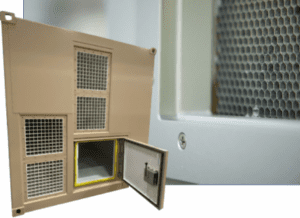
Figure 3: RF shielding waveguide point-of-entry protection (Gaven) 2.4 Electrical Filters
Waveguides are integrated into shielded enclosure designs to facilitate the movement of air, water, fuel, fiber-optic cabling. RF signals, and other support elements to pass from outside the shield to the interior of the shield or vice versa without compromising the integrity of the shield These follow particular electromagnetic principles that depend upon the material or waveform passing through the waveguide as well as the physicaldimensions of the waveguide.
When properly engineered, this allows, as an example, air forventilation to pass through a shielded wall without compromising its requirements for shielding against electromagnetic energy, such as that contained in at HEMP event. Throughout the consultation and design process, firms that offer EMP consultation such as Gaven Industries will work with architectural and engineering disciplines to identify and recommend waveguide requirements for the enclosure or facility.
More often than not, shielded enclosures need to be connected to a power source Conductors required to facilitate power and control signals must pass through the shield However, once a conductive cable passes. through a shield, it compromises the shielding significantly because E-threat energy can couple to cables/wires and travel through the shield, where it will "reradiate," allowing harmful energy inside a protected area. Previously described conditions can be avoided by appropriately selecting passive points of entry where copper conductors pass through electrical filters before entering the shielded volume. Most often, this requires using a "Low-Pass Electrical Filter, which uses capacitors and inductors to create a condition where control and power signals can pass through the shield When applying a HEMP-rated electrical filter, the HEMP energy, which is much higher in frequency than traditional power signals, cannot pass without being significantly reduced in magnitude. These are readily available for many different applications by commercial vendors. When this is the case, an experienced EMP consultant is the key to successful planning for EMP protection and mitigation.

Figure 4: HEMP-shielding door inside Gaven Modular Enclosure Structure
Shielded facilities that require personnel to work in the protected space must
facilitate means of access Special shielded doors that, when closed, exclude E-threat energy have been designed, fielded, and qualified. When these pass-throughs are installed in interlocked pairs, it provides the means to obtain access to a shielded volume without compromising the shield integrity by opening a single door. Commonly, access hatches and emergency exit doors must also be part of a shield for maintenance, emergency egress, and operational purposes These follow similar principles to exclude electromagnetic energy.
3. Substation EMP Resilience
Substations, in practice, contain many pieces of equipment and apparatuses that allow them to interface with transmission and distribution lines safely. However, “Substation Resilience” inevitably focuses on the nerve center of the substation, the Substation House The substation house will generally contain communications equipment, backup power systems, protective relays, and control equipment. The relays and controls must interface with equipment in the rest of the substation yard. Historically, this has meant that copper cabling must be routed from equipment in the yard to the appropriate protective relay or control system located in the substation house. As shown in the figure below, these cables could be thousands of feet long.
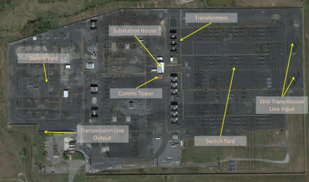
The substation house should be protected from electromagnetic threats. The level of protection required has been subject to analysis and studies from diverse organizations such as the Blectric Power Research Institute, and the Defense Threat Reduction Agency. Some conclusions have been based on “Small Volume E-1 radiated emissions testing and some have been based on “Pulse Current Injection Testing”.
Conclusions reached based on realistic simulated environments have been limited. During an EMP, energy hits a substation house (and all the equipment inside of it) virtually simultaneously-radiated emissions from the air and conducted emissions from signal and control cables (through common-mode coupling) would hit, for example, a protective relay at the same time. Some testing indicates modest tolerance to EMP energy on the part of some protective relays. However, this approach it is not complete, because the test environment provided is different than the EMP environment that substation house components are required to survive.
Some testing published on substation house resilience has been performed using ML-STD-188-125-1 Appendix A. This test methodology does notilluminate sufficiently substation house signal and control cables, so therefore these test results potentially provide an overly optimistic performance view of effective substation resilience. It is these cables - signal/control/power that limit the performance of even a substation house shielded against radiated emissions of an EMP.
In EMI there is a source, a path, and a receptor (or victim). There are several types of paths or methods of transmission of EMI from the source to the receptor. Radiated EMI happens when a high-power transmitter or electrical device produces a radio frequency that is picked up and causes unwanted effects in another device. If there is EMI and the source and receptor are far apart, then it is likely radiated EMI. Some examples of this would be a broken kitchen microwave causinga computer to reboot or old wireless telephones causing WiFi to drop.
Radiated EMI can be subdivided into narrowband and broadbandinterference.
- Narrowband EMI only affects a specific radio frequency and is commonly from a radio transmitter.
- Broadband EMI affects a large portion of the radio spectrum at many frequencies and is commonly caused by malfunctioning equipment. Wireless telephones causing Wi-Fi to drop is an example of radiated electromagneticinterference.
Conducted EMI happens when there is a physical electrical path from the source to the receptor. This is often along power transmission lines Some sources may be a large motor or power supply. An example of conducted EMI is the turning on of a treadmill or clothes dryer causing a computer on the same electrical mainscircuit to reboot.
Coupled EMI happens when the source and receptor are close together, but not electrically connected
Coupled EMI can be transmitted through induction or capacitance
- Inducted or magnetically coupled EMI happens when a conductor's magnetic field induces an unwanted current in a nearby conductor. An example of inducted EMI is when a power cable and an audio cable are near each other, and a hum is heard on the audioline.
- Capacitively coupled EMI happens when two conductors are parallel and store a capacitive charge between them Capacitively coupled EMI requires the conductors to be very close together and is most common on electronic circuit boards or in groups of closely packed wires running long distances.
To ensure the utmost protection against radiated emissions, significant shielding for substation houses is required Architects should utilize shielding solutions that are designed to meet the risk mitigation standards outlined in MIL-STD-188-125-1, effectively reducing electromagnetic interference, and minimizing the risk of disruptions caused by external sources.
To mitigate conducted emissions threats, designs should incorporate methods that emphasize the integration of protection measures into substation house cable entryways. Transmission of unwanted electrical signals can be effectively managed by grounding and filtering conducted EMI at the cable point of entry.
EMP and EMI fiters should be used for power systems. within the substation house. These filters effectively suppress electromagnetic disturbances, safeguarding the substation's power infrastructure from the detrimental effects of electromagnetic interference.
To enhance the resilience of backup power systems during extended outages caused by an EMP or EMI event, operators may consider the addition of a shielded generator. Even a modest-sized generator, equipped with adequate electromagnetic shielding, can significantly extend the Black Start timeline, ensuring continued power supply during critical situation.
Data communications must also be E-threat resilient in a properly protected shielded enclosure. Fiber Optic repeater Regen stations must be placed at approximately 50 to 100-mle intervals. Bandwidth breakout points may be required much more frequently.
Each of these "nmodes" must also implement proper electromagnetic shielding if an E-threat-shielded data center is to remain functional otherwise, there is a significant risk that the data center will not remain operational and become "islanded" such that it cannot communicate with the outside world.
Gaven Industries and its partners have developed options for regen and breakout sites that provide E threat resilience to fiber optic communication nodes.
Gaven advocates the utilization of test methods that demonstrate more realistic conducted emissions, specifically focusing on common mode emissions of cables entering substation houses By employing these comprehensive testing methodologies such as those outlined in MIL-STD 188-125, shielding effectiveness can be accurately evaluated in real-world scenarios, guaranteeing reliable and robust performance.
4. Conclusion
Shielding providers such as Gaven, offer the capability to create both prefabricated permanent and semi permanent modular shielding solutions for substation houses of various sizes for all types of interference. In either case, both of these options are cost-effective full envelope shields that ensure comprehensive protection from electromagnetic threats.
For existing substation houses or on a smaller scale, Gaven can provide RF and HEMP-shielded data racks and smaller-scale enclosures for key technology.
These specialized solutions allow for the targeted shielding of protective relays, communications, and even backup power systems within the substation house. This approach enables efficient and swift. implementation, minimizing downtime and reducing costs.
New approaches are available to shield all aspects of critical infrastructure associated with the Bectric Power Grid Blectromagnetic Threats are not expected to go away. In the near future, it is likely that regulation will require E-threat protection for many, if not all, Critical Infrastructure areas. Shielded Substations will be an essential component of complete E-threat resilience Gaven Industries is at the forefront of designing and furnishing E-threat solutions that are cost-effective, reliable, and sustainable.
White Paper: EMP & IEMI Protection Concepts For Transmission & Distribution Substations




About Us
Gaven Industries specializes in EMI, EMP, HEMP, and RF shielding solutions, including expertly crafted doors, shielded structures, rooms, and data racks.

Quick Links
Stay Informed
Subscribe for exclusive updates
and insights from Gaven Industries.
Copyright © 2024 Gaven Industries Inc. All Rights Reserved.
